Whole-system integration
Not 15 tools. One system, from the first requirement to the last board off the line.
Connecting a few instruments is a protocol problem, and it was solved decades ago. This is the other thing: a product specified, designed, simulated, made testable, tooled, qualified, scheduled, costed, fabricated, inspected, tested on a line and then watched in the field — with what each stage produces being read directly by the next, in a published format, rather than being carried across in a meeting.
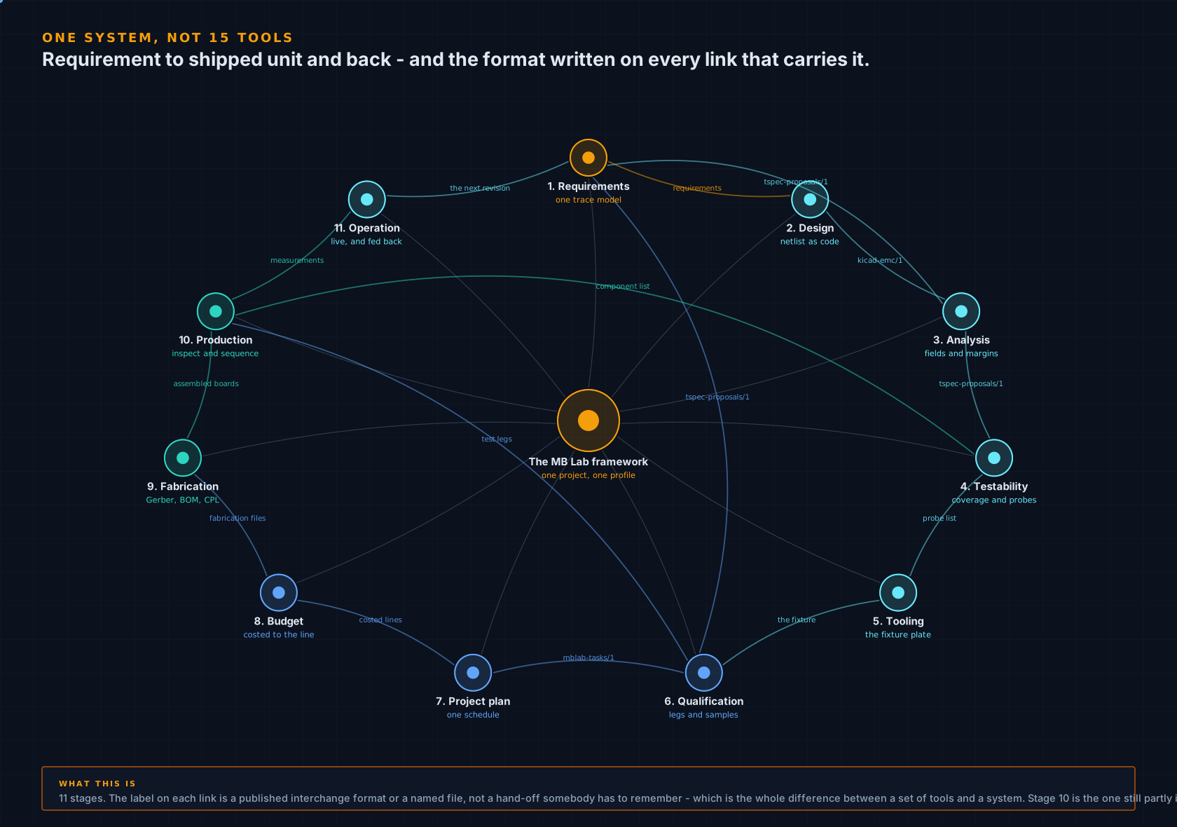
What makes it a system
A spine, not a drawer of tools that happen to share a logo.
Every one of these applications reads one product profile — industry, markets, product class, environment — and writes what it knows in a format the others already read. A predicted emissions failure becomes a test case with a parent requirement. A coverage analysis becomes a fixture drawing and then an inspection recipe. A qualification plan becomes tasks, and the tasks become a costed schedule. Nothing in that chain is a person re-typing the previous stage's answer, which is the step that actually fails in small teams — not the analysis.
Stage 10 is the one still partly in the pipeline, and says so below. What each one speaks →
The arc, stage by stage
Eleven stages, and what each one hands to the next.
Two of these are the ones small shops usually do last, in a spreadsheet, under time pressure: the project plan and the budget. Here they are outputs of the same run as the engineering, because the applications that know how long a chamber booking takes and how many samples it needs are the ones writing the tasks.
-
1
Requirements
What the product has to do, and what has to be proven about it, held in a form a tool can read instead of a document somebody has to remember. Design documents, test analysis results and imported requirements link into one model, and every later stage is traced back to it.
What comes out. Trace model, ReqIF for DOORS and DOORS Next, StrictDoc, OpenFastTrace, Kiwi TCMS, and AI instruction sets - one complete run of it is published on this site, unedited
-
2
Design
The board itself: the netlist written as code, a schematic generated from it with wired and labelled nets, placement, routing and pours - then ERC, DRC, schematic parity and test access run as release gates rather than offered as opinions.
What comes out. KiCad project, hardware design specification, system specification and design review package, each as a web page, a Word document and a PDF
-
3
Analysis
Before anything is built: a 3-D full-wave solve of the structures that matter, gated by a mesh check because a bad mesh returns a confident wrong answer - and an EMC pre-compliance pass against the standards this product's industry and markets actually impose.
What comes out. S-parameters and Touchstone, line impedance checked against the closed form, predicted emissions and immunity margins with the failing and flagged tests named, and the layout review that goes with them
-
4
Testability
Whether a probe can reach every net, and what each component's coverage really is across in-circuit test, flying probe, boundary scan, optical inspection and functional test - measured per part rather than argued from experience.
What comes out. PCOLA/SOQ coverage workbook, the unreachable nets named, and suggested test points as a paste-ready snippet that goes back into the layout
-
5
Tooling
The bed-of-nails plate the coverage analysis has just planned, located on the board's own mounting holes so the datum is something a machine shop can actually find, and drawn per plate rather than per board.
What comes out. Machining DXF, dimensioned drawing, Excellon drill file, STEP model, hole centres as XYZ, push-rod and force tables, and a pin table naming the net and target of every probe
-
6
Qualification
Which environmental and mechanical tests the industry, the markets and the mounting location require, how many samples that needs, and whether the test legs really run in parallel - which is the question that quietly costs a quarter when the answer is no.
What comes out. Sample matrix, test legs, test plan, per-setup instructions, report template, equipment list and schedule
-
7
Project plan
Every application writes its own tasks against the same milestone ids, so four workstreams merge into one schedule instead of four reports that somebody reconciles by hand in the week before the design review.
What comes out. 116 tasks and 558 hours in a single Microsoft Project file, with the dependencies between workstreams already drawn
-
8
Budget
What the plan costs before it is promised to anyone: chamber hours at an hourly rate with the technician hours beside them, equipment coming out as two thirds of the bill, and an LCSC part number on every line of the bill of materials so the build cost is a figure rather than a guess.
What comes out. 17 tests, 38 samples, 88 days and USD 125,103 costed per line, 502 hours of climatic chamber, and 42 pieces of equipment reconciled across four applications
-
9
Fabrication
The files a fabricator and an assembly house actually take, in their own column formats - and, for the first article, a prototype board cut in the lab on a fiber laser rather than waiting on a courier.
What comes out. Gerber zip, drill, bill of materials and pick-and-place in the assembler's format, STEP for the mechanical fit, and laser artwork with a calibration coupon for the in-house prototype
-
10
Productionpartly in the pipeline
On the line: optical inspection run against the same component list the coverage analysis used, and a test sequence built from the qualification plan's own test legs rather than written again from scratch. The sequencer is released and drives a bench today; the in-circuit and functional stations it will drive are designed and in the pipeline, which is the only part of this ring that is.
What comes out. Inspection verdicts per board, a sequence with limits and an on-failure behaviour per step, and a JSON, CSV and HTML report per unit without being asked
-
11
Operation
The bench and the line keep reporting: live values into a spreadsheet cell, onto Modbus, OPC UA and MQTT, plotted beside an analogue channel on one timebase. What comes back is what the next revision's requirements are written against, which is why this is a ring and not a line.
What comes out. Live data into spreadsheets and dashboards, logged history behind a disk queue, decoded waveforms, and tags re-served to whatever reads next
DataStreamerX · HardwareRTD · SignalScope · MBLT PLC · MBLT HMI
Planning and money
The schedule and the bill are generated, not guessed.
This is the part that is usually missing from engineering software and present in project software, with a person in between. Each application writes its tasks against shared milestone ids; the dispatcher merges them into one Microsoft Project file with the cross-workstream dependencies already drawn; the qualification costing prices the same plan to the line, with equipment coming out as two thirds of the bill. Change the design and run it again — the schedule and the cost move with it instead of going stale quietly.
Against one real board, with four applications installed. How the dispatcher merges them →
On par with a department
Ten desks a deliverable usually comes from.
A large organisation does not get its advantage from better engineers. It gets it from having somebody whose whole job is the traceability matrix, and somebody else whose whole job is the qualification schedule, and a third person who prices it. A shop of one or three has the same deliverables to produce and nobody to hand them to, so they get produced badly, late, or not at all. Every row below is a deliverable this set produces as a file, from the same project, in one run.
| The desk | What it is there to produce | What produces it here |
|---|---|---|
| Requirements engineer | the trace model, the traceability matrix, ReqIF out to DOORS | Test Spec Ecosystem |
| DFT and test engineer | per-component coverage, the probe plan, the fixture drawing set | PCB Test Analysis |
| EMC engineer | the applicable standards by market, pre-compliance margins, the layout review | EMC Design Compatibility |
| Simulation engineer | the full-wave solve, S-parameters, impedance against the closed form | EM Solver |
| Qualification engineer | the sample matrix, the test legs, the validation schedule | Validation Testing |
| Technical author | the test plan, the specification, the per-setup instructions, the report templates | Test Spec Ecosystem |
| Project planner | the task list, the dependencies, one Microsoft Project file | MB Lab Dispatcher |
| Cost estimator | the costed plan and the equipment bill, to the line | Validation Testing |
| Test automation engineer | the station, the sequence, the limits, the per-unit report | MBLT Sequencer |
| Quality engineer | the inspection recipe and the verdict per board | AOI Inspector |
This is not a claim that software is as good as a specialist, and it should not be read as one — a good EMC engineer will beat a pre-compliance estimate every time. It is a claim about what exists at the end of the week when there is no EMC engineer to ask.
The spine itself
Six formats, and nothing hidden behind them.
These are what make the arc one system rather than eleven tools in a row. They are plain documented files, so anything you write can read them or write them, and an application nobody here has heard of can join the chain without a single change to the others.
mblab-apps/1
What each application is, what it reads and what it writes. The dispatcher derives the run order from this rather than being told it, which is why the sixteenth needed no change anywhere.
mblab-tasks/1
Project tasks against shared milestone ids. Every application writes it; one Microsoft Project file comes out of all of them.
tspec-proposals/1
Test cases proposed into the trace model. EMC and validation both write it, so a predicted failure becomes a test case with a parent requirement instead of a note in a slide.
kicad-emc/1
The layout findings the EMC analysis needs - ground plane, return path, decoupling, stitching - written by the tool that read the board.
emsolve-result/1
A finished full-wave solve with its mesh verdict attached, so an EMC margin can say which number it trusted and why.
mblab-equipment/1
What the bench actually has. Reconciled across applications, and read by the sequencer as the station's hardware.
What I actually believe
Tenfold — and I am calling that a belief, not a measurement.
Everywhere else on this site I refuse to put a multiplier on any of this, because nobody has run the same board through the same project twice with a stopwatch, and a number invented to sound good is worth nothing. So read this paragraph as what it is: my own opinion, signed, and kept separate from the figures.
In my own work the difference is not a few per cent. It is an order of magnitude — tenfold, and on the documentation more than that. Not because any single analysis is dramatically faster, but because the handovers disappear: the reconciliation, the finding out whose copy is current, the re-typing of one stage's answer into the next stage's form, and the weeks that follow a failure found late. What that buys is not only speed. It is capability — work that a one-person shop simply could not take on before, because producing the evidence was a bigger job than doing the engineering, is work it can take on now.
The checkable version of the claim is the rest of this page: eleven stages, 6 formats, 15 applications, one profile, 103 files and one project plan out of a single run. Make your own multiplier out of those — and if you have taken a board through both ways, I would far rather publish your number than mine.
The same comparison without the opinion, question by question → · Send me your two numbers →
Being built now
The set is not only software.
The applications specify a fixture, a sequence, a bench and an enclosure. These are those things being built: the instrument a fixture bolts into, the tester that runs the functional leg, the sequencer that drives it, and the printer that makes the parts. None can be downloaded or bought yet, and none of them has anything to photograph. They are here because each one closes a gap you can already see in the pages above, and because saying what is coming is more useful than letting it arrive as a surprise. No dates — a date I miss is worse than no date at all.
Test equipment
In-circuit test equipmentBeing designed
The tester that the fixture files already describe.
What already exists. PCB Test Analysis already produces the whole fixture from the layout: a machining DXF of the plate, a dimensioned drawing, an Excellon drill file, hole centres as XYZ, a probe list with the net and target of every pin, the push-rod table, the force report, and a STEP model of the plate for the mechanical assembly. Those files go to a shop today.
What is missing. What is missing is the instrument the plate bolts into - the receiver and interface board, the switching matrix, and the measurement front end that reads what the probes touch. It is being designed against the boards on the hardware page, because those are the boards whose coverage has already been analysed.
Test equipment
Automated functional testersBeing designed
The bench that runs the functional leg, built as a unit.
What already exists. The functional test leg already exists on paper: Test Spec Ecosystem writes it out of the trace model as P-FT, with the cases, the limits and the equipment each one needs, and MBLT Sequencer can import that leg and run it. The instruments are reachable already - SCPI, Modbus, VISA, the HardwareRTD engine - and the simulated bench proves a sequence against faults before any hardware exists.
What is missing. The bench itself, as one thing rather than a trolley of borrowed instruments: a modular tester carrying programmable power, an electronic load, a relay matrix for routing, and the sensor and signal simulation a board needs to be exercised. It is being designed around the sequencer that would drive it and the fixtures the coverage analysis already specifies, which is the only reason to build it rather than buy one.
In-house manufacture
Rapid prototypingBeing set up
Enclosures, jigs and fixture plates made here, from the same files.
What already exists. The enclosures on the hardware page are drawn and exported - STEP for assembly, DXF for flat parts - and the fixture plates come out of the coverage analysis in the same formats. Laser engraving and fibre-laser copper ablation for prototype boards are already done in-house.
What is missing. What is being set up is printing them here rather than sending them out: enclosures, probe pods, panel parts, assembly jigs and fixture plates, on a day's turnaround instead of a week's. Until that is running, the hardware page says of every enclosure that it is designed and not yet printed, because it is.