Software — emc

EMC Design Compatibility

Find the emissions failure on your bench, not in a rented chamber.

Early release 0.1.1 emc — command line and desktop app

What it does

Works out which EMC standards apply to your product for its industry and markets, estimates radiated and conducted emissions and immunity against those limits, and produces the test plan, the equipment list and the test instructions for each set-up.

  • Applicable standards by industry and market — FCC for the US, CE for Europe
  • Radiated and conducted emissions and immunity estimates with margins
  • ESD, EFT/burst, surge and BCI set-ups
  • Near-field and far-field simulation - a Biot-Savart |H| scan above the board, 2-D FDTD including the enclosure and its apertures, and a far-field radiation pattern
  • Ports modelled individually - kind, nominal voltage, cable length and position on the board - because that is what radiates
  • Reads the PCB Test Analysis result and the design requirements, and hands test cases on to Test Spec Ecosystem
  • Test plan, equipment list and per-set-up test instructions
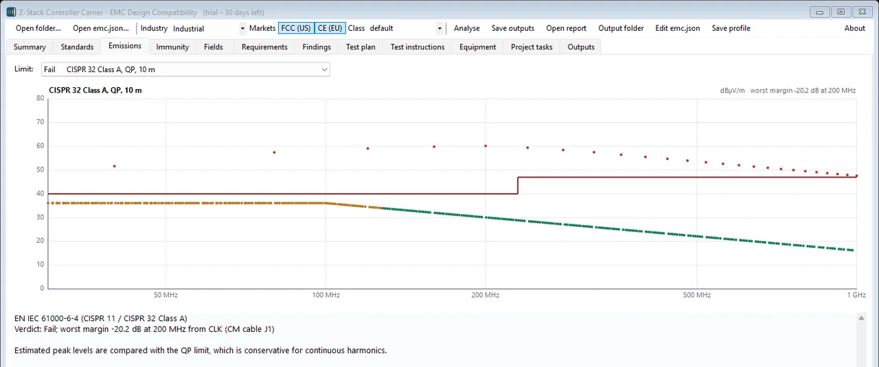
Estimated emissions against the CISPR 32 Class A quasi-peak limit. This board fails by 20.2 dB at 200 MHz, traced to the clock on a common-mode cable.
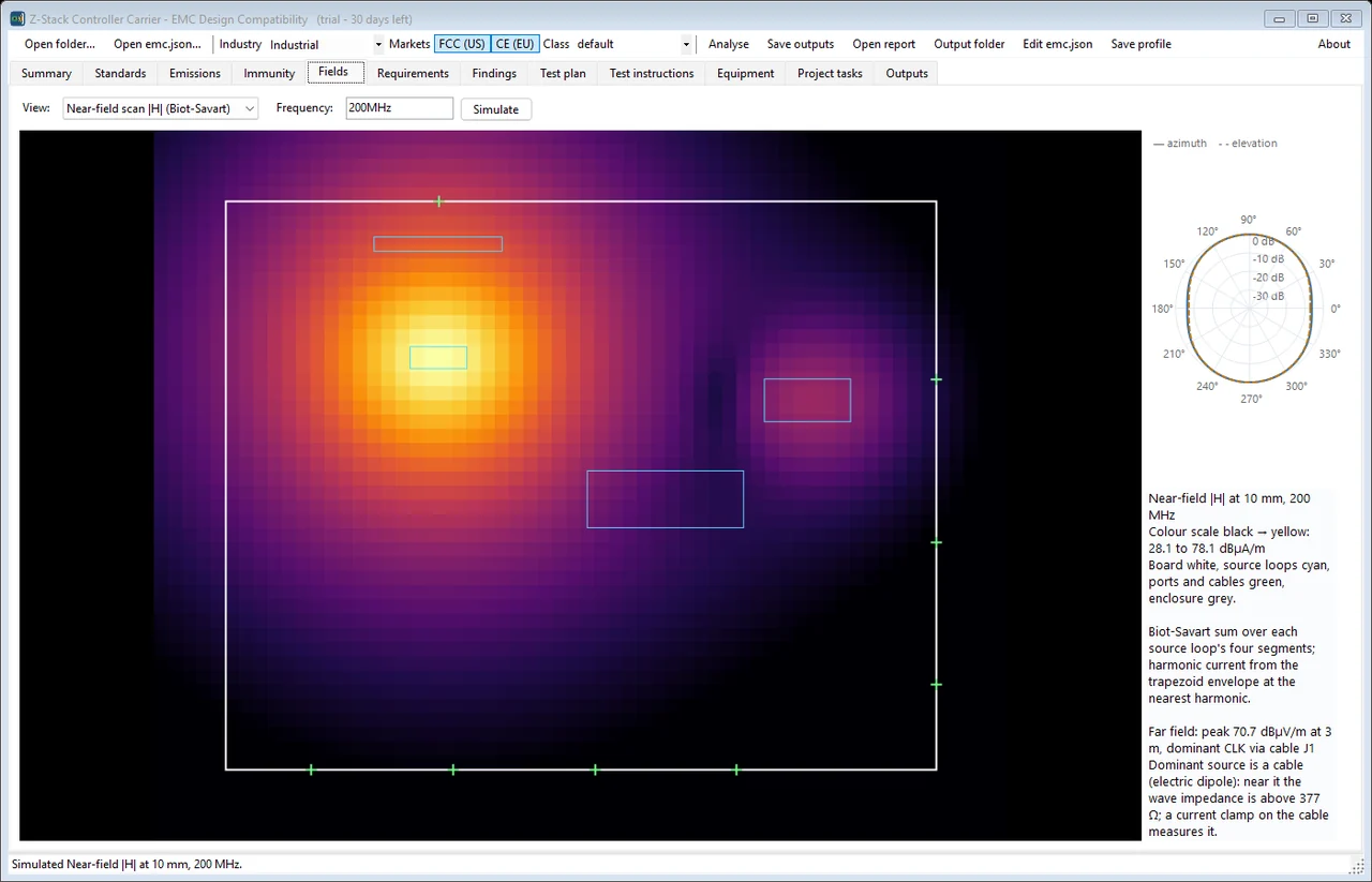
The same board's fields at 200 MHz. Left: simulated near-field |H| at 10 mm by Biot-Savart summation, 28.1 to 78.1 dBµA/m, board outline in white and source loops in cyan — the hot spot is where a sniffer probe would find it. Right: the far-field pattern, peaking at 70.7 dBµV/m at 3 m, dominated by the clock radiating off cable J1.
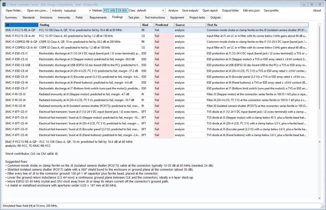
The Findings tab for the same board: every predicted failure with its standard, kind and margin, and a first fix on the same row. Selecting one prices the fix - the worst contributor here is the clock via the common-mode cable on J8, where a choke or clamp ferrite typically buys 10-20 dB at 80 MHz and 24 dB is needed, so the shield bond, connector filtering and ground return inductance are listed with it.
The Test plan tab: nine set-ups with their phase, hours, predicted result and margin - and which can stay on an in-house pre-compliance bench against which need an accredited ISO/IEC 17025 laboratory, the line that decides the budget. Each row carries the id of the test instruction generated for it, and selecting one shows its standard, equipment and entry and exit criteria.
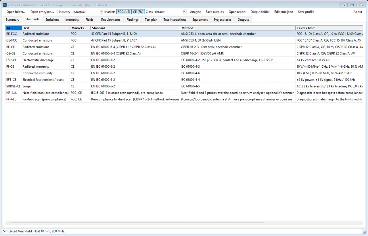
Which standards actually apply, worked out from the industry and the markets rather than chosen from a list. Eleven rows: FCC Part 15 subpart B for the US, EN IEC 61000-6-4 and 61000-6-2 for Europe, and the IEC 61000-4 series behind each immunity test - each with its measurement method and the level or limit it has to meet, down to +-4 kV contact for ESD and 10 V/m from 80 MHz to 1 GHz for radiated immunity.
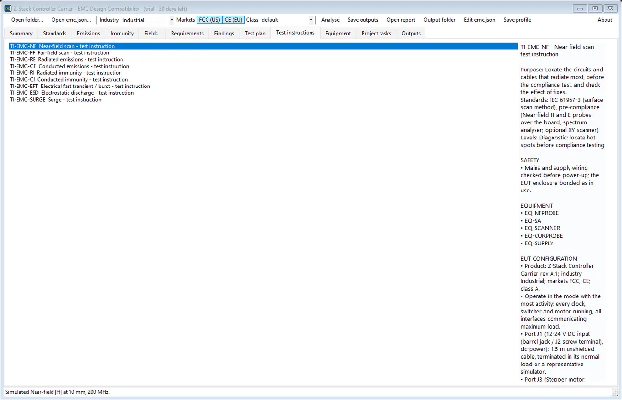
A test instruction per set-up, written for the person who has to run it. Purpose, the standard and method, the level and criterion, a safety section, the equipment by id, and the EUT configuration - which mode to operate in, and what to do with every cable, port by port. Nine of these come out of one analysis, and they are the pages that go in the folder beside the bench.
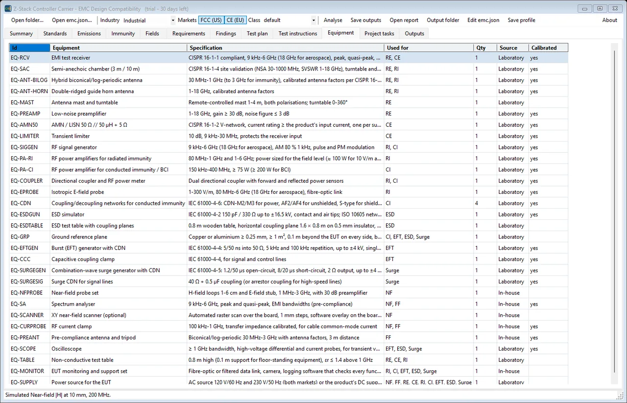
The equipment the plan needs, specified rather than named: a CISPR 16-1-1 receiver from 9 kHz to 6 GHz, a site-validated semi-anechoic chamber, an ESD simulator to +-16.5 kV, the right LISN for the product's input current. The Source column is the one that decides the budget - it splits what an accredited laboratory has to provide from what can stay in-house, and the Calibrated column says which of it needs a certificate.
The same analysis as a project plan: six phases from preparation through design fixes, pre-compliance, emissions, immunity and the market documents, with hours, start and finish days, predecessors and the resource each task needs. A milestone marks pre-compliance complete. This is what exports to Microsoft Project XML, and what merges with every other application's tasks into one plan.

On video

One recording of it actually running.

A screenshot of a program that moves is only half of it, so here it is moving. Recorded off the screen while it ran on this bench - its own window, its own example project, nothing staged. The verdicts are whatever the application returned. Nothing plays until you press it.

40 s The same board against the standards its industry and markets impose. Emissions test by test with the margin in dB; immunity port by port, the worst of them 57.2 dB short at the USB input. Then a near-field scan simulated while you watch - the board as a heat map at 200 MHz with the source loops outlined and the far-field pattern beside it - and the test plan and equipment list that come out of all of it.

Get in touch

EMC Design Compatibility is not a download. It is one of the tools the work is done with, installed and licensed when an engagement starts. Tell me what you are working on and I will tell you what it would do for it.

Or email mblab.technology@gmail.com. Your details are used to answer you and to follow up — nothing else.

Requirements

  • Windows 10 or 11, 64-bit
  • About 200 MB of disk
  • No .NET install needed — the runtime is bundled
  • No Excel needed — workbooks are written directly

Also in the set